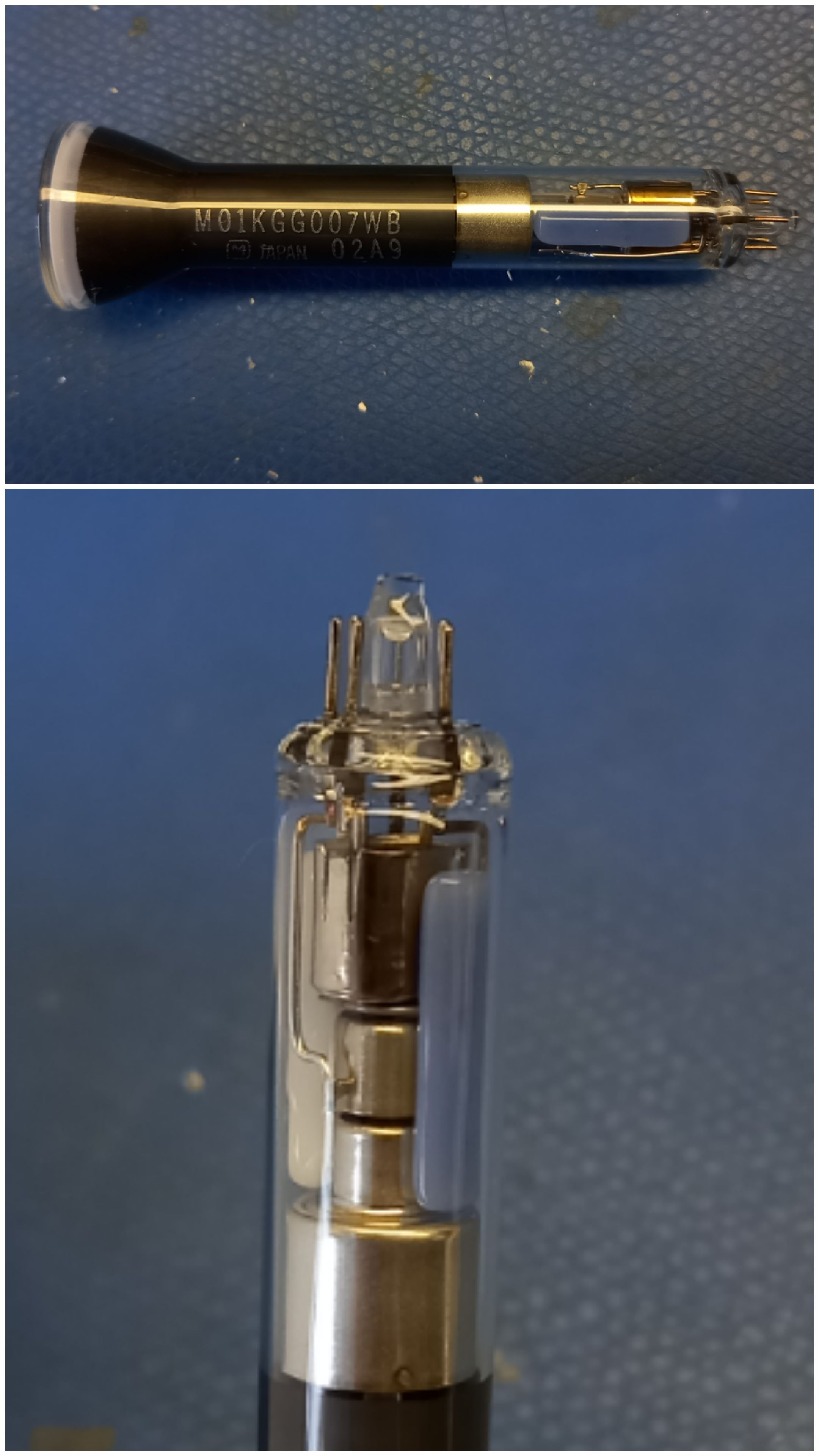
ELY07V552J Viewfinder CRT
Found these little gems in a local surplus store. This is my journey to making these display work.
Exisiting information
Found a post that pointed to a schematic for the device that these CRTs was used in.
CRT the first
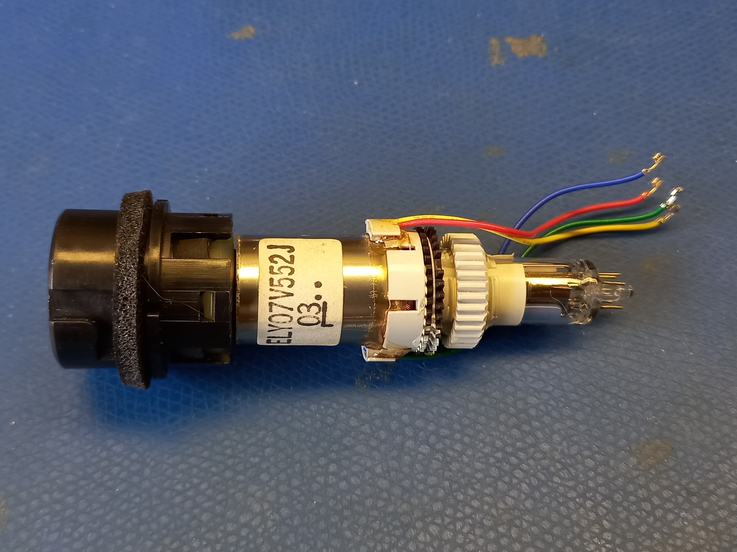
First thing I wanted to find out was the what each pin is.
Observations:
- Pin 3 and 7 measure 20Ohm
- All other pins are isolated
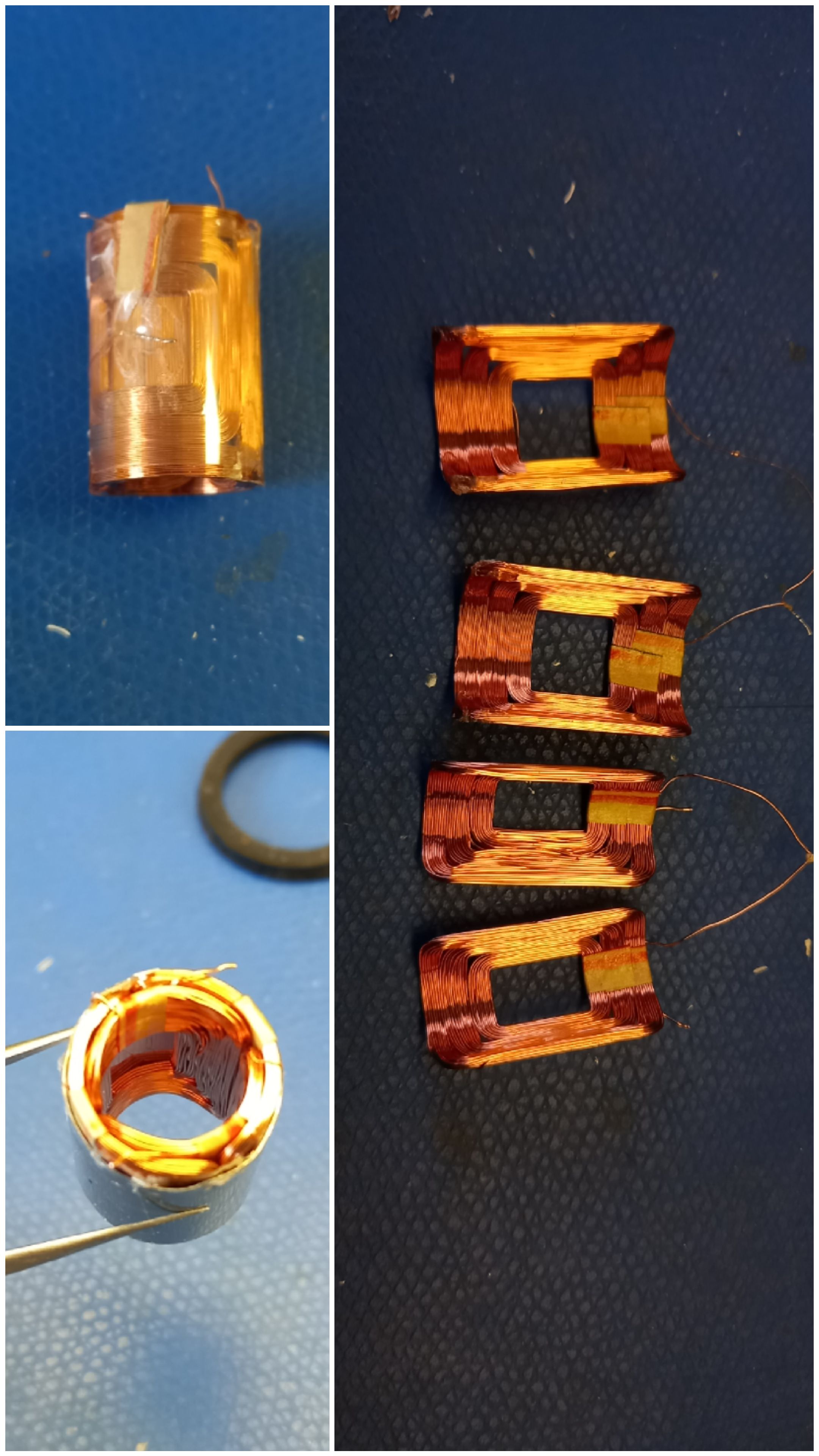
- Scanning with magnetic deflection with (red, blue) and (yellow, green) as the coild pairs in the yoke.
It would be safe to assume pin 3 and 7 are connected to the heater so I hooked it up to a power supply and cranked the current. I was hoping to measure the resistance increase as the heater heats up but I looked up for a second and the heater went open circuit. The limit was at 15mA so I guess we have an upper limit and a tube I don't feel bad about tearing it down.
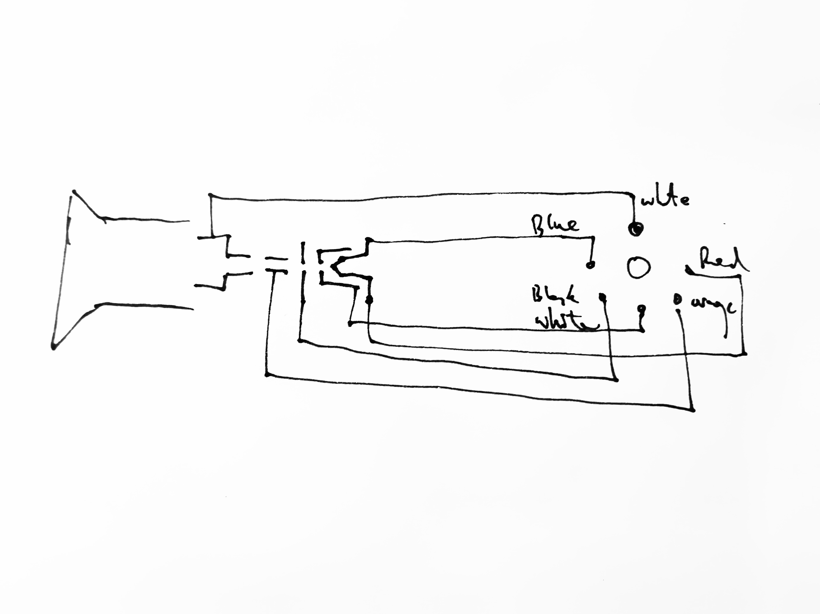
For the remainder of this post I'll try to use the following names listed in order of which an electron whould pass:
| Name | Pin # | Wire | Description |
|---|---|---|---|
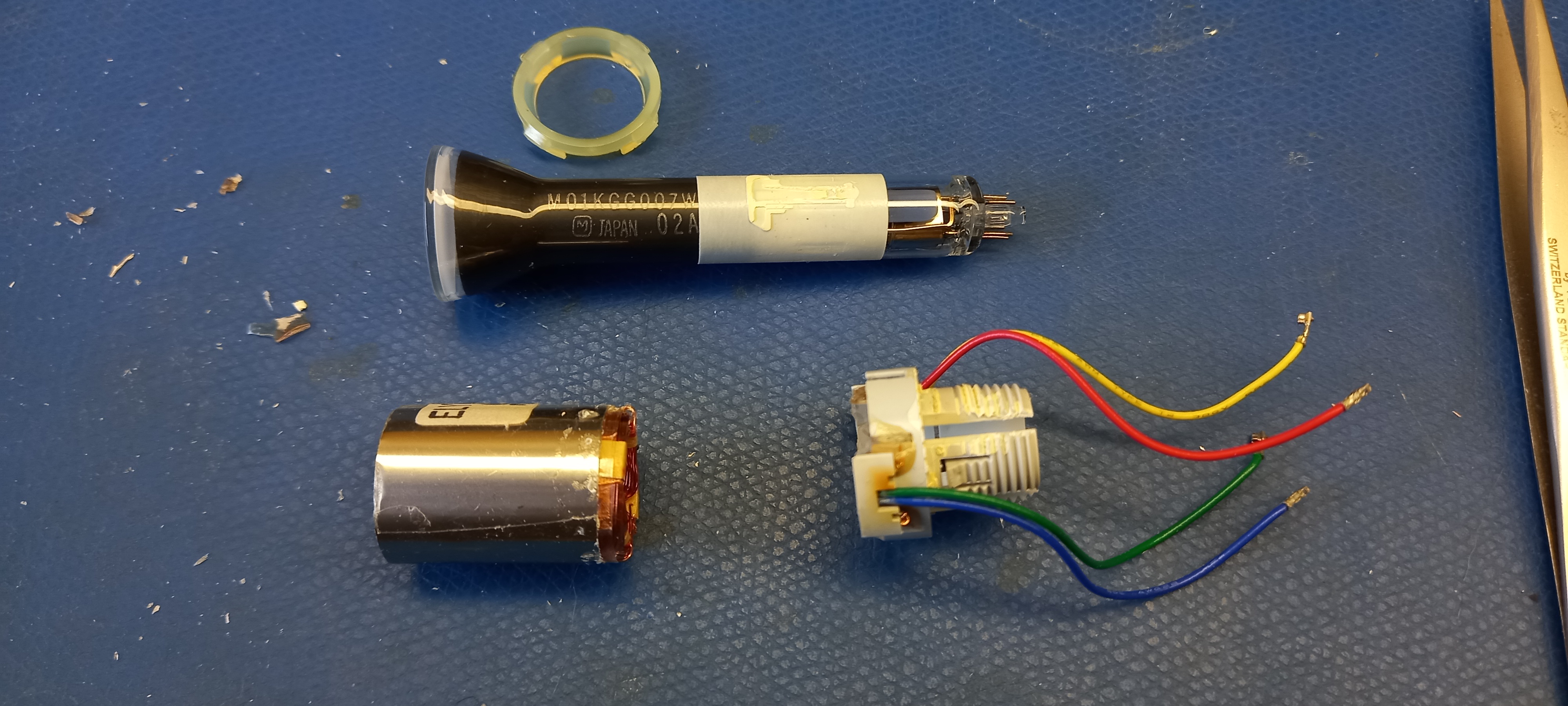
| Heater | 3,7 | thin red & blue | Heater and cathode. |
| Grid | 5 | thin white | Can surrounding the heater. |
| Anode1 | 6 | thick black | Thin disk with small apeture. |
| Anode2 | 4 | thick orange | Tube section. |
| Anode3 | 1 | thick white | Final anode going all the way to the screen. |
CRT the second (first light)
With every learnt from the first tube, I broke out the second one.
I started with the heater hooked up to a modest 5mA, grid floating, anode 1 to ~20% HV, anode 2 to 50% and anode 3 to HV souce via a ~10MOhm resistor divider.
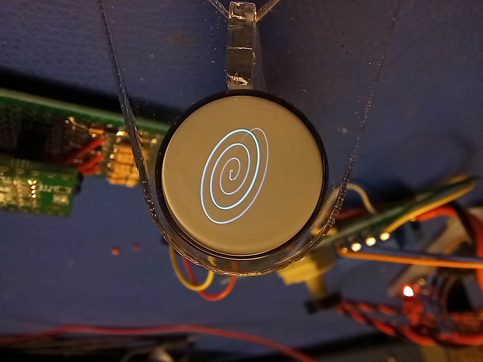
Increasing the HV power supply to ~2KV yeilded first light! The spot decreased brightness really quickly and I found it was due to the floating grid. Tying it to the heater resulted in a stable light output. Tweeking around the voltage got an nice pattern that looks like an image of the cathode's willingness to shed electrons.
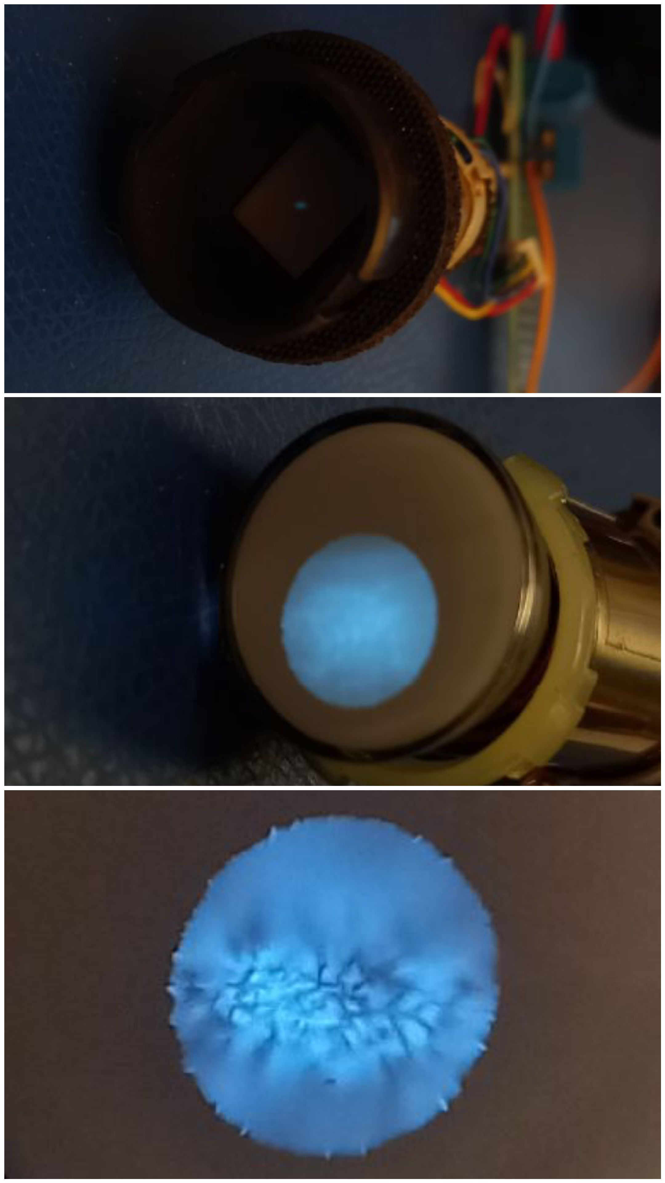
After playing around with creating a dedicated HV supply for this project and playing with anode voltages I was able to get a dot small enough to try drawing some patterns.
The focus is still really bad so time to do some reading:
Focus
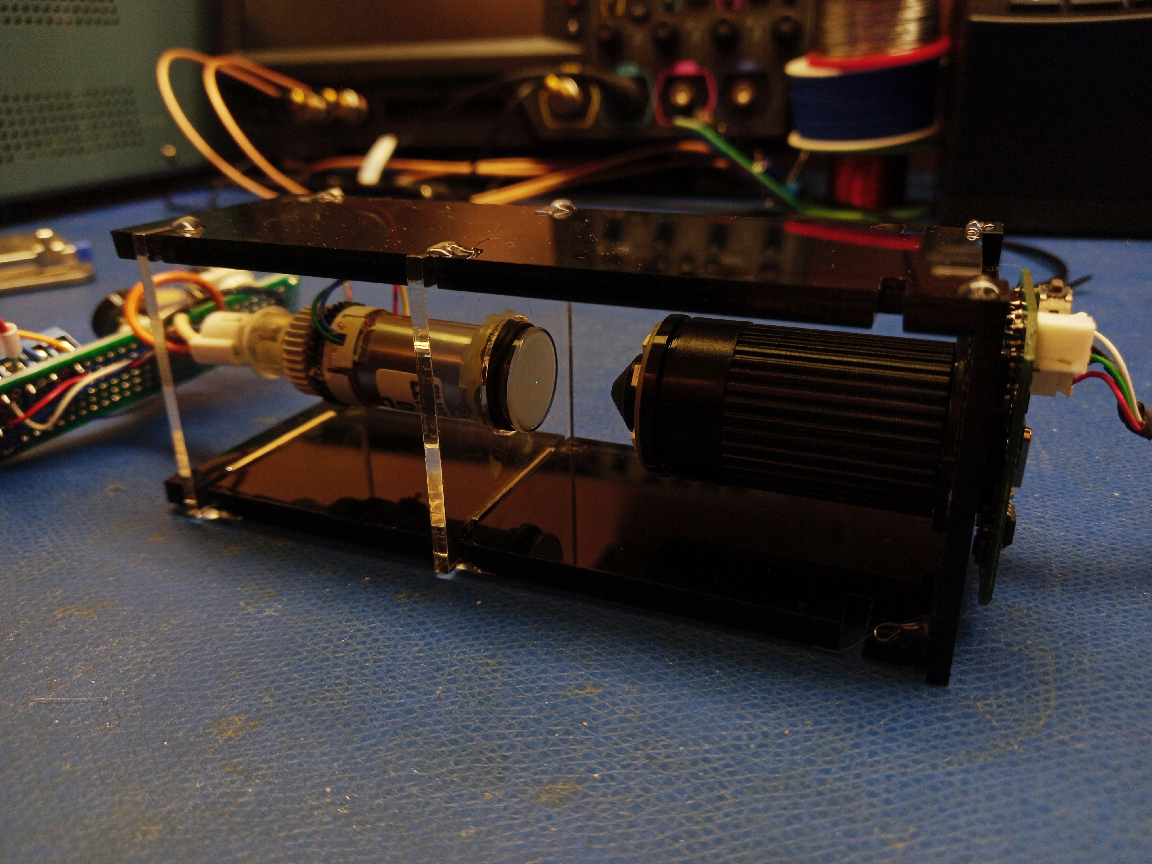
It has been hard to determine the change of spot size as I tried different settings especially when they occur across a power cycle, so I made a quick jig that held the tube and pointed a microscope USB cam at the screen.
With an easily comparable metric, I started to navigate through the search space. Whenever I reached the extent of the trimmer pot, I would solder in an extra resistor to offset the range. All this lead to a focused and bright enough spot to start thinking about controlling the spot to do more than patterns.
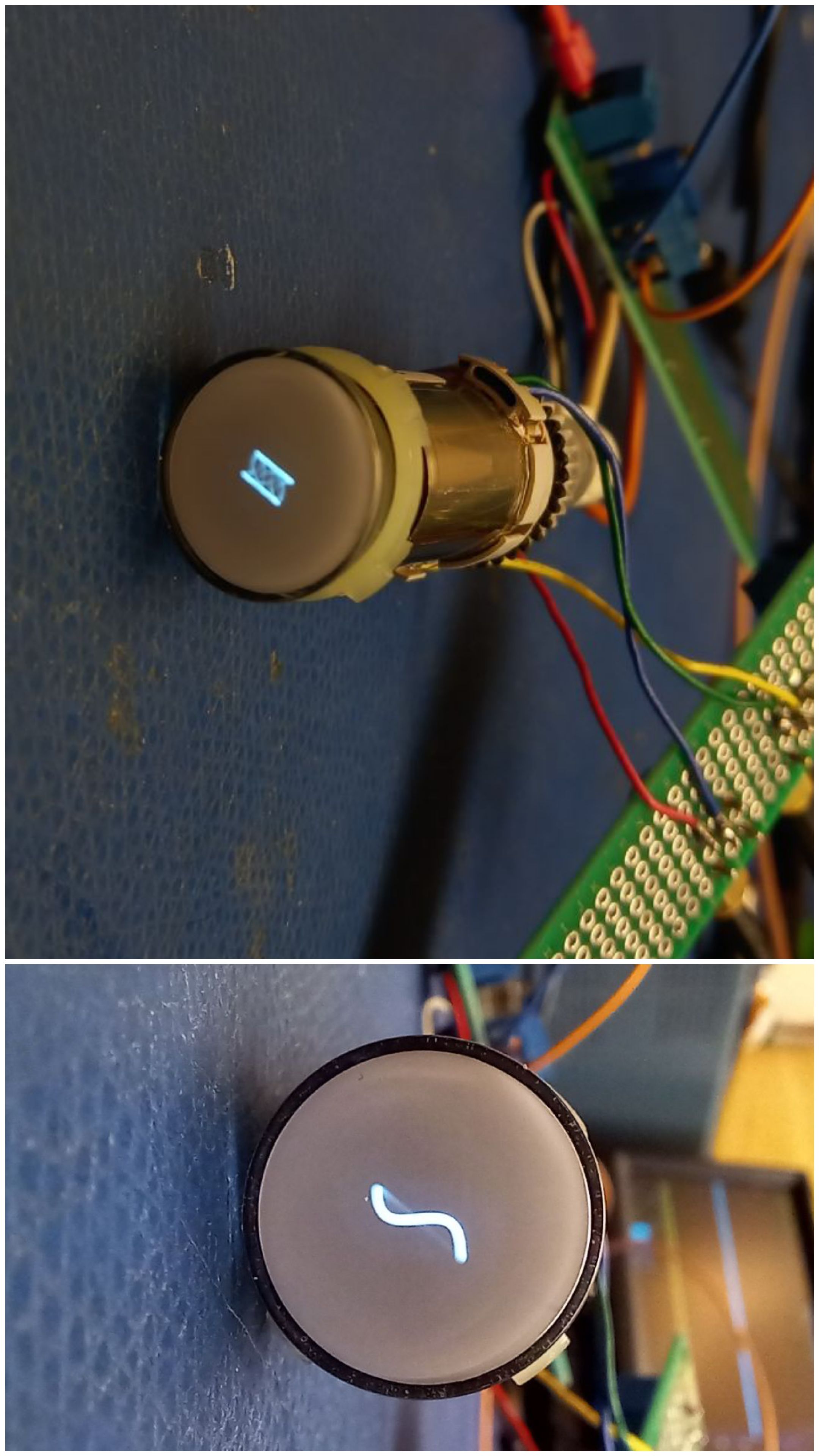
DACs
I didn't feel like buying DAC ICs and amplifiers to drive the coils. I also didn't want to have a negative rail in the system. Ideally everything would be driven off a single 12V supply. For the coils it was trivial with a class-D amplifier and a low pass filters. I had some MOSFET gate drivers with hight enough current rating and worked with pulses down to ~10ns. With 4 channels (2x2channels ICs) I was able to drive coils in both directions is a H-bridge config on each coil. The PWM clock was ~500kHz so I added a LPF with a cutoff at ~200kHz and called it good.
The negative rail for the grid was used to control the intensity of the spot. This was a little more interesting, a lot of designs online used op-amps with a negative rail and subtracted the positive DAC output with reference to ground. While I had some op-amp around that can handle the ~200kHz bandwidth, but there is no other justification to create a negative rail and a lot more silicon than I had room left on the protoboard. So I modified a common negative rail generator circuit to enable a PWM signal to set the negative rail to be a percentage of the input voltage. I was lucky here as the grid is very high impedence so I didn't have to worry anout any regulation to compensate for the load current.
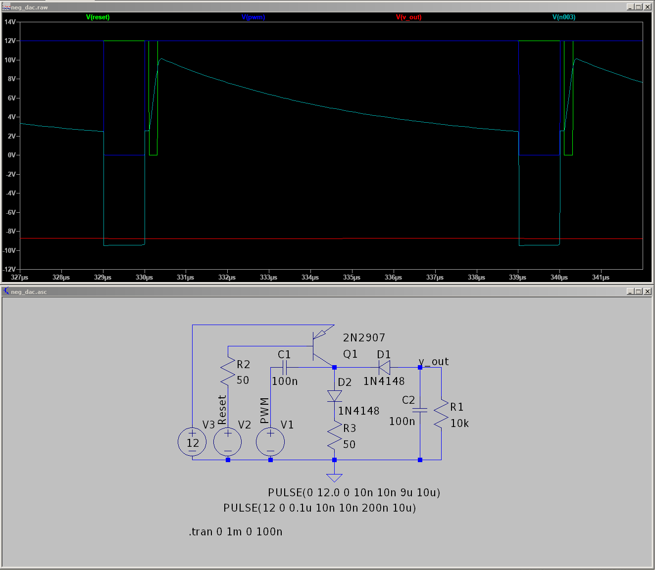
Major differences to the typical negative voltage generator is R3 added to the charging path for the C1. This allows the charge on C1 to be controled by the pulse width of V1. Q1 was added to fully discharge C1 at the start of each cycle. For driving the V1 and V2, I used another dual channel MOSFET driver IC.
To control all of this I opted to use an iCEstick ice40 FPGA dev board. It handles the 500kHz PWM no trouble and allowed introducing the reset signal for the negative DAC which is a little more annoying to do with the PWM/compare cores in microcontrollers.
I had some modules already for loading data from serial to the build in RAM so all that was left was to get the DAC to read the RAM and we have arbitary patterns!