Micro EMP
One thing lead to another. I found an intersting SMD transformer on mouser. Built a HV (not very HV, like 600V HV) power supply from it. And stuck a thyristor between HV caps and a small coil. Next thing I knew, I had everything I needed to try out some EM fault injection.
HV source
The transformer I found was the TDK ATB322515-0110, a 1:10 step up transformer. Quick testing showed the transformer can ring up to ~300V peak after driving the primary nearly saturate the core.
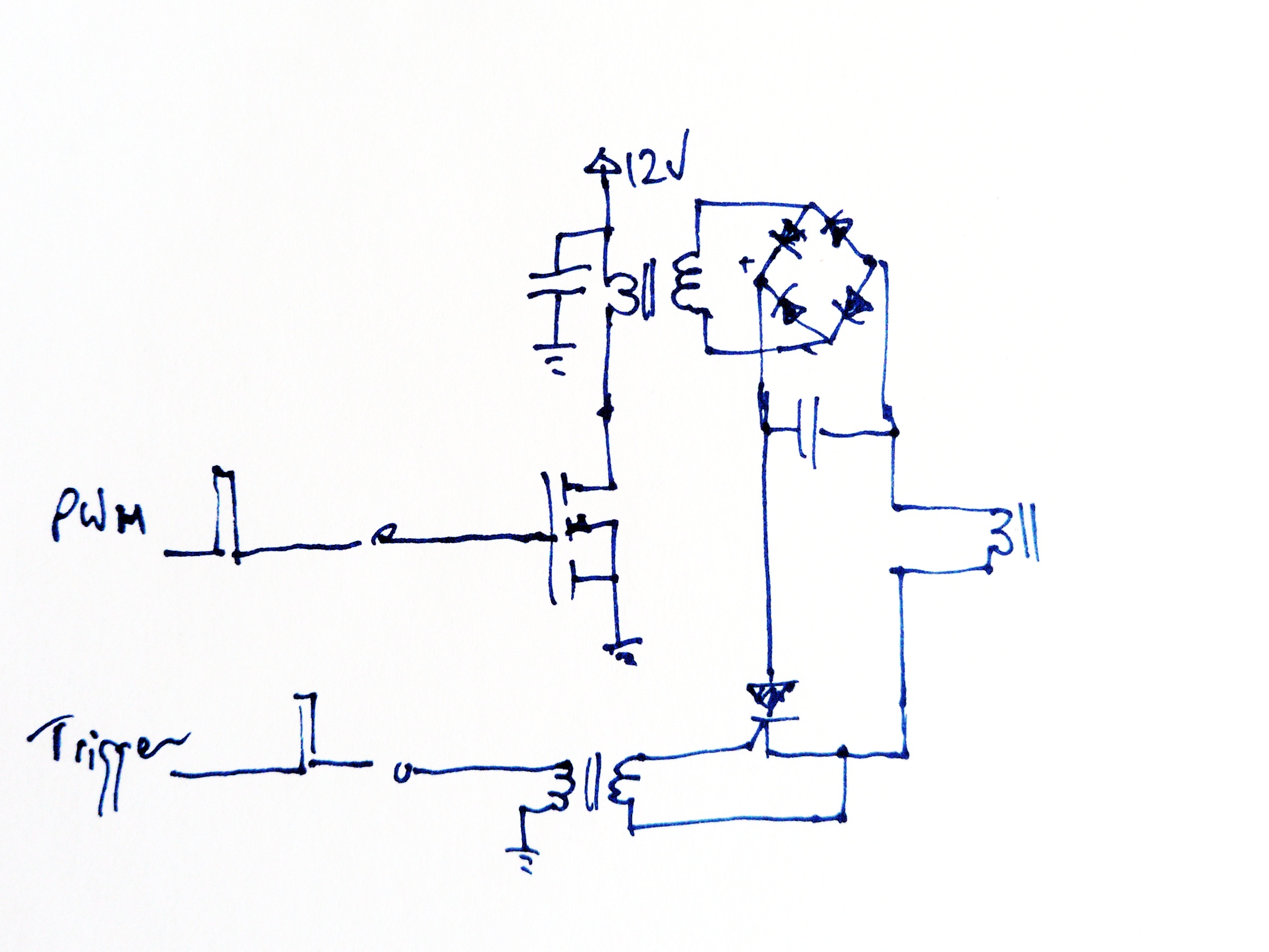
I did end up putting two step up stages in series to get up to 600V output. The output HV cap are some 47nF 1kV X7R ceramics I had lying around. I didn't have any 600V rated mosfet so I settled for a thyristor. And threw on a random 1:1 signal transformer with 1kV isolation rating to keep the HV side isolated.
EM fault poc
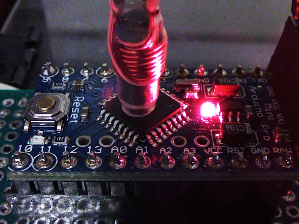
Ground down some ferrite rods I had to have a small point on one end. Put a few turns of wires on it and stuck it on the HV supply. With a small loop at the end of a coax hooked up to my scope, I was getting a ~200ns pulse when held near the EMP head. This gave me enough confidence to point it at an arduino and see what happend.
Using a Arduino Pro mini, with an external FTDI serial to USB. This ensures the serial comms is as far from the EMP head as possible. The Arduino was running a simple incrementing a register. Then reporting the value of the register. If the EMP worked, we would either skip instructions or change memory value. This should be visible as a change of reported value. Using asm here to avoid having to think about what the compiler is trying to optimize. With a 8 bit a, a complete inc_a_256 should leave the a unchanged. If any instruction is skipped or memory changed then a will change. I repeated the inc_a_256 to fill as much of the program memory. Then looped long enough so it runs on the order of seconds. Making timing of fault injection easier.
volatile uint8_t a = 0;

#define inc_a asm volatile("inc %[a]":[a]"+r"(a))
#define inc_a_10 inc_a;inc_a;inc_a;inc_a;inc_a;inc_a;inc_a;inc_a;inc_a;inc_a
#define inc_a_100 inc_a_10;inc_a_10;inc_a_10;inc_a_10;inc_a_10;inc_a_10;inc_a_10;inc_a_10;inc_a_10;inc_a_10
#define inc_a_256 inc_a_100;inc_a_100;inc_a_10;inc_a_10;inc_a_10;inc_a_10;inc_a_10;inc_a;inc_a;inc_a;inc_a;inc_a;inc_a

void setup() {
  Serial.begin(9600);
  Serial.println("INC test");
  for (uint32_t i=0;i<5000;i++){
    inc_a_256;
    inc_a_256;
    inc_a_256;
    inc_a_256;
    inc_a_256;
    inc_a_256;
    inc_a_256;
    inc_a_256;
    inc_a_256;
    inc_a_256;
  }
  Serial.println(a);
}
Preliminary results
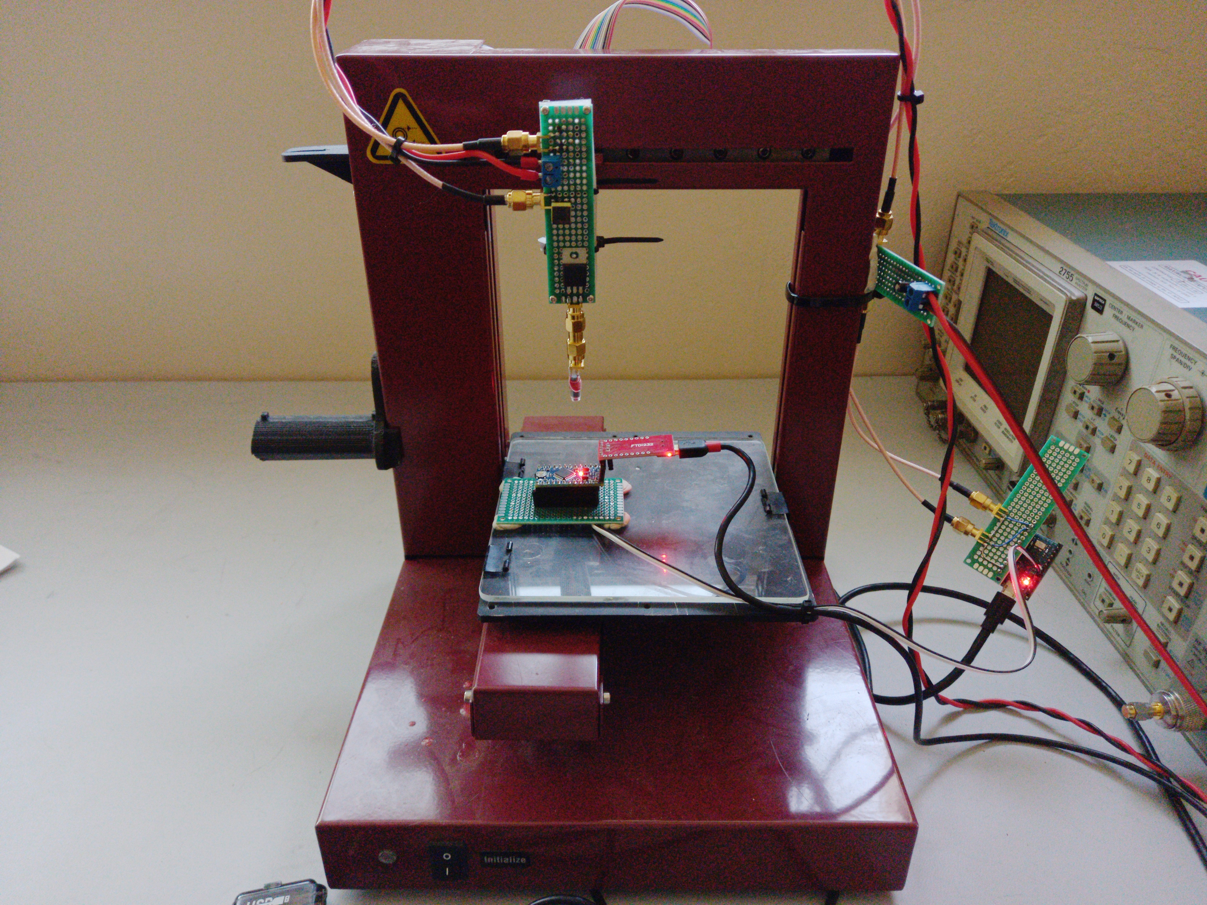
Time to put this EMP on an XYZ stage to see which part of the micro is the most susceptible to the EM fault.
Sweeping the head over the MCU on and plotted. Each data consist of 10 restart of target MCU followed by 10 faults injected every 0.5s.
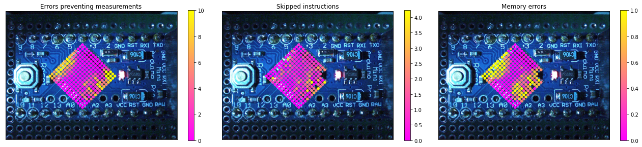
What I didn't expect here is that the areas on the peripheral of the MCU is more susceptible than the center. This might suggest that the fault might be injected by induced currents on the bond wires or traces on the PCB?